
 Latest images
Mon Jul 08, 2013 3:56 pm by Admin
For the benefit of 944Hybrids users there are two search functions available for you to use.
The purpose of this sticky is to explain the "Advanced Search" function because it is much more powerful and is the best choice when researching information.
When you log on to the site a list of options is shown in a line at the top of the page. One option is labelled "Search", use this option (NOT the search box lower down on the right).
After you click on the upper search option, a drop down box appears. At the bottom of this box is a radio button marked "Advanced …
Comments: 0
Ray's 1987 944 LS1 Build & Swap
Page 4 of 14 •  1, 2, 3, 4, 5 ... 9 ... 14
 ![]()
Axle Shaft Replacement Options???
![]() Raymond-P Thu May 27, 2021 3:37 pm
Raymond-P Thu May 27, 2021 3:37 pm
However, while packing up my tools for the evening I began to contemplate clean-up and rehab of the rear crossmember and a suspension rehab. What a mess... especially the original axle shafts. They're rusted and the boots appear to leak somewhat.
[You must be registered and logged in to see this image.]
Rear crossmember and suspension - After Pressure Wash
It dawned on me that replacing the CV joints makes sense considering all the other drivetrain work.
So....my question for the forum experts is this:
What is the option of choice (based on experience) when replacing the axle shafts for LSX applications?
Pricing is all over the place with budget providers expounding on how much better their product is than OEM, while the high-dollar suppliers boast that their product is produced by the OEM manufacturer. Then there is the custom axle option with stronger carriers, bigger joint components, and special alloy shafts.
I did spend some time doing custom searches of the forum and learned much but I wasn't able to pick up on a consensus. Perhaps that's just because we're all doing slightly different things with our cars.
For me, I'm planning some "mostly for fun and charity event" track time and regular street use.
Price wise, a pair of new axle shaft assemblies for under $200 would be great if they actually hold up.
But I only want to do this once the right way...so I'm willing to go higher on the price.
I'm going to keep researching my options, but I respect and look forward to some input from the forum.
Thanks in advance!
Raymond-P- Posts : 385
Join date : 2013-06-29
Age : 68
Location : Beaver, PA
Re: Ray's 1987 944 LS1 Build & Swap
![]() sharkey Thu May 27, 2021 10:45 pm
sharkey Thu May 27, 2021 10:45 pm
i think your only off the shelf option would be the lindsey racing/drive shaft shop axles. they have axles using either 100mm type 2 style joints (stock size), or they have a 108mm 930 style axle and use adapter plates. your going to spend $1200-$1600 going with these axles.
the option i chose when i was running the porsche transaxle was to build a set of axles using empi parts. i used empi type 2 offroad cv joints and empi chromoly axle shafts. the axle shafts require machining for the inner clips (the offroad buggies this stuff is intended for dont run an inner clip, but id recommend it on a car). in the end i think i was a little more than half the cost of the lindsey racing/dss axles, and they worked out great. i do have a thread somewhere here detailing what it took.
all that being said, axles in these cars typically dont break from too much torque, its either worn out joints failing or a worn out transaxle mount causing too much movement, that binds the axle and causes a failure. you could clean your axles up, take apart and inspect the joints and if the races and balls look good rebuild them with a new set of boots and some good grease, or get some new oe replacement joints.
sharkey- Posts : 714
Join date : 2014-11-21
Age : 39
Location : Abbotsford BC
Re: Ray's 1987 944 LS1 Build & Swap
![]() Raymond-P Thu May 27, 2021 11:44 pm
Raymond-P Thu May 27, 2021 11:44 pm
sharkey wrote:all that being said, axles in these cars typically don't break from too much torque, its either worn out joints failing or a worn out transaxle mount causing too much movement, that binds the axle and causes a failure. you could clean your axles up, take apart and inspect the joints and if the races and balls look good rebuild them with a new set of boots and some good grease, or get some new or replacement joints.
Sharkey,
Thanks for the input! I've assessed and reconditioned my transaxle mount already and it's in A1 condition with no cracks or distress in the rubber or vulcanization.
[You must be registered and logged in to see this image.]
The factory axles feel solid with no discernible play and they turn smoothly. Plus, I don't recall any noise from them in turns or whatever, even when I was auto-crossing the car.
Your advise is sound as always and it makes sense to disassemble the axles to see exactly what I have. Since my car is an '87 I'm not even sure if I have the old or new shaft spine count!
When I was doing my research, I did read your thread on building an Empi axle & CV joint system, including the machine work, and it was impressive. There was no recent update on how the system was performing but based on you comment here, it sounds like a great solution moving forward.
If in the end I have axle problems before transaxle problems I'll likely be following your lead.
Raymond-P- Posts : 385
Join date : 2013-06-29
Age : 68
Location : Beaver, PA
Re: Ray's 1987 944 LS1 Build & Swap
![]() spence Fri May 28, 2021 2:36 am
spence Fri May 28, 2021 2:36 am
spence- Posts : 684
Join date : 2009-07-21
Age : 41
Location : St.Catharines, Ontario, Canada
Re: Ray's 1987 944 LS1 Build & Swap
![]() Leva Fri May 28, 2021 6:17 am
Leva Fri May 28, 2021 6:17 am
Leva- Posts : 82
Join date : 2020-04-04
Re: Ray's 1987 944 LS1 Build & Swap
![]() Hotrodz of Dallas Fri May 28, 2021 9:38 am
Hotrodz of Dallas Fri May 28, 2021 9:38 am
$450 a pair plus shipping.

Hotrodz of Dallas- Posts : 615
Join date : 2015-10-31
Age : 65
Location : Dallas-Ft. Worth
Re: Ray's 1987 944 LS1 Build & Swap
![]() Raymond-P Fri May 28, 2021 4:18 pm
Raymond-P Fri May 28, 2021 4:18 pm
spence wrote:[You must be registered and logged in to see this link.]
Thanks Spence!
Looks like I could upgrade for $550 plus about $100 for new boots & CVJ grease, plus tax, and shipping. Then there is the machine work for the inner retainer clip. Grand total I'm guessing would be somewhere in the $800 - $900 range. Definitely an option.
Raymond-P- Posts : 385
Join date : 2013-06-29
Age : 68
Location : Beaver, PA
Re: Ray's 1987 944 LS1 Build & Swap
![]() Raymond-P Fri May 28, 2021 4:20 pm
Raymond-P Fri May 28, 2021 4:20 pm
Hotrodz of Dallas wrote:For anyone interested, I can get brand new GKN turbo axles for $225 each. Same supplier to Porsche for the 944.
$450 a pair plus shipping.
Thanks Bob! That looks like a really competitive price. I'll keep this in mind if my axle disassembly turns up some damage.
Raymond-P- Posts : 385
Join date : 2013-06-29
Age : 68
Location : Beaver, PA
Hotrodz of Dallas likes this post
Transaxle "Make-Over" Complete
![]() Raymond-P Thu Jun 03, 2021 9:50 pm
Raymond-P Thu Jun 03, 2021 9:50 pm
The 5P transaxle is looking good... all cleaned, blasted, primed, and painted!
[You must be registered and logged in to see this image.]
Before
[You must be registered and logged in to see this image.]
After
I spent some time cleaning up the speedometer sensor and it seems to be mechanically functional. Since the 5P is a "used" piece and was sitting around for awhile, the contacts really needed some attention. Here are some pics for those that haven't ever seen one closeup....
[You must be registered and logged in to see this image.]
Since the TA case was exceptionally grimy around the axle flanges I've decided to replace both the axle shaft seals which likely were leaking. I opted for a seal kit on Ebay from Ian at 944Online with 1 main shaft input seal - 2 differential axle seals, the shift rod lever seal, and 2 oil cooler loop seals (O-rings). I also scored a pair of oil cooler loop clamps that I needed. From what I could gather, the parts are OEM but once I get them I'll provide an update.
6-18-2021 UPDATE
My seal kit arrived while I was away. As I hoped, the seals were all quality units:
1 main shaft input seal - DPH (brand), Germany, 25 40 8 , 111525
I did not disassemble my transaxle so I won't be using this seal anytime soon.
2 differential axle seals - Elring (brand), Germany, 45x60x8, 379311
1 shift rod lever seal - DGS (brand), 16 24, 6/6 S, Austria, 012 301 457 C, 18, KA3, Bar Code: 928 303 120 01
2 oil cooler loop seals (O-rings) - Porsche OE, PN: N 028 203 3
2 oil cooler loop clamps - Porsche OE, PN: 951 307 379 00
The seals listed above all came in a "kit" put together by the folks at 944OnLine and sold by IanPorsche on Ebay. [You must be registered and logged in to see this link.]
I must admit, this kit was ideal for me as there are so many options online for buying the seals separately, but you never know if you're getting a quality OEM product and the pricing varies wildly. Not only that, most sellers hit you with excessive shipping costs as much or more than the cost of the product.
[You must be registered and logged in to see this image.]
<TA Axle and Oil Cooler Seals, and Cooling Tube Looms>
[You must be registered and logged in to see this image.]
<Shift Rod Lever Seal>
Inspection of the axle shaft CV joints is next.... after a brief vacation that is.
In the mean time, this is what my drivetrain is looking like:
[You must be registered and logged in to see this image.]
Last edited by Raymond-P on Fri Jan 06, 2023 1:03 pm; edited 2 times in total (Reason for editing : Parts Update, Photo Update)
Raymond-P- Posts : 385
Join date : 2013-06-29
Age : 68
Location : Beaver, PA
Mystery Component???
![]() Raymond-P Fri Jun 18, 2021 5:03 pm
Raymond-P Fri Jun 18, 2021 5:03 pm
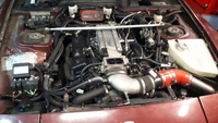
I'm back from vacation in FL and beginning a full prep of the engine compartment. In the process of removing the radiator overflow tank and head light motor and linkage, I came across a mickey mouse set up for a solenoid or relay of some sort that appears to reside behind the driver's side headlight. Mine was actually mounted on the outside such that in was just in front of the inner fender. See below:
[You must be registered and logged in to see this image.]
View from inside the engine bay. Note I do have the plastic/hard rubber plug.
[You must be registered and logged in to see this image.]
Solenoid outside the engine bay...seems odd.
[You must be registered and logged in to see this image.]
The silver relay is clearly a flasher but my Italian is insufficient to define the "Accumuatori Alto Adige"
The car has been in a light front end fender bender at one time and the person putting it back together appears to have just improvised the mounting using some galvanized strap.
Can anyone tell me the function of this component and the proper mounting?
Thanks in advance!!!
Raymond-P- Posts : 385
Join date : 2013-06-29
Age : 68
Location : Beaver, PA
Re: Ray's 1987 944 LS1 Build & Swap
![]() spence Sat Jun 19, 2021 2:48 am
spence Sat Jun 19, 2021 2:48 am
spence- Posts : 684
Join date : 2009-07-21
Age : 41
Location : St.Catharines, Ontario, Canada
Re: Ray's 1987 944 LS1 Build & Swap
![]() Hotrodz of Dallas Sat Jun 19, 2021 9:17 am
Hotrodz of Dallas Sat Jun 19, 2021 9:17 am
Hotrodz of Dallas- Posts : 615
Join date : 2015-10-31
Age : 65
Location : Dallas-Ft. Worth
Re: Ray's 1987 944 LS1 Build & Swap
![]() Raymond-P Sat Jun 19, 2021 11:31 am
Raymond-P Sat Jun 19, 2021 11:31 am
I didn't know the car was so equipped!!

Curiously, the wiring is located in a stock position along the top of the driver's side fender and disappears into a maze of wiring that goes behind the power brake booster. I'm guessing this may be the original wiring for the emergency flashers??
Below is what the other end of the "pump" looks like and it appears to have an air intake and output nozzle, but I would say the owner never connected a horn to it.
[You must be registered and logged in to see this image.]
Covering the installation was a rubber fender port filler bolted to the pump but not positioned in the fender. It does fit perfectly in the fender but now has a hole in it. Not a big deal to remedy but I'm curious what the access port is actually for. Any thoughts?
[You must be registered and logged in to see this image.]
Inside view Outside view
In conclusion... I see no reason why I should keep this unit and I think it's headed to the bone yard. Thanks for the input!!
Raymond-P- Posts : 385
Join date : 2013-06-29
Age : 68
Location : Beaver, PA
AC Considerations
![]() Raymond-P Sun Jun 20, 2021 12:35 am
Raymond-P Sun Jun 20, 2021 12:35 am
1) The AC compressor must be relocated to the passenger side where the LS block has provision for mounting brackets. No room on the driver's side anyway with the PS pump and alternator.
I’m not exactly sure if I can use the Porsche compressor with custom brackets or a late model compressor with line adapters.
[You must be registered and logged in to see this image.]
Note: The wiring harness for the front lighting (Z) will be relocated to the top of the fender to avoid header heat and free up a bit more space. I noticed after posting this that the clutch hydraulic line is also in the picture and shouldn't be. It's the one with the mounting bracket attached.
2) The #10 low pressure AC return line from the evaporator to the compressor (A) must to be replaced and relocated to the passenger side where the compressor will be. It will also need to be shielded from the header and will be significantly shorter. I still need to figure out how to make the connection at the firewall as I need a straight fitting vs. the stock 90-degree fitting. Advice is always welcome.
[You must be registered and logged in to see this image.]
3) The stock condenser, dryer, the small #6 high pressure AC return line (C) that runs on top of the driver's side fender from the dryer to the evaporator, and the high-pressure line (D) from the dryer to the condenser can remain.
[You must be registered and logged in to see this image.]
4) The #8 high pressure discharge line (B) from the relocated AC compressor (now on the passenger side) to the condenser must be replaced and relocated under the condenser to the stock connection on the driver's side.
Below is a plumbing diagram that I pulled off the forum years ago when I first started this adventure. I don't know who to credit but it appears somewhat accurate. I created a digital version from a notebook sketch for improved clarity. I do not profess to be an AC expert so if something looks amiss, please advise. I did notice a couple of differences on my car: 1) the hose lines in and out of the compressor are the same size and the high side port is located very near the compressor.
[You must be registered and logged in to see this image.]
I’m looking forward to some suggestions from the forum and I will continue to research. In the meantime, to facilitate a good clean-up of the engine bay, I’m going to remove the components of the AC system that I know I won’t be using.
Happy Father’s Day to all you dads out there!!! I’ll be back on the project on Monday.
Last edited by Raymond-P on Sun Jun 20, 2021 12:52 am; edited 1 time in total (Reason for editing : Added info.)
Raymond-P- Posts : 385
Join date : 2013-06-29
Age : 68
Location : Beaver, PA
smkn951 likes this post
Hydro-Boost Install - Part 1
![]() Raymond-P Thu Jul 08, 2021 12:09 am
Raymond-P Thu Jul 08, 2021 12:09 am
The time had come to remove the existing brake power booster and install my new TPC HB kit. This was definitely not something I was looking forward to as “shoe-horning” my 6 ft 185 lb. self under the dashboard is not my idea of fun.
[You must be registered and logged in to see this image.]
<TPC Hydro-Boost Kit>
First, I disconnected the brake lines from the master cylinder and removed the master cylinder. I will be reusing this on the hydro-boost for proper brake line pressure proportioning. For now it gets set aside for a complete clean-up and possible rebuild.
[You must be registered and logged in to see this image.]
<Original Master Cylinder and Reservoir>
To get the power booster off, you must access the three (3) retaining nuts under the dash. This requires removing the steering wheel which was simple enough…I pried off the horn pad with a large flat blade screw driver, working each corner carefully until it “popped off.” That was the hardest part! A single horn wire must be disconnected. The 24 mm nut (with wave washer) that holds the steering wheel on came off easily using an impact wrench. A replacement 3-spoke contemporary wheel is in the works…
[You must be registered and logged in to see this image.]
<Steering Wheel Off> <Under the Dash>
[You must be registered and logged in to see this image.]
<Under Dash Bolt Locations>
The Forum recommendation was to remove the driver’s seat too, but I have power seats and my electrical system is disconnected completely. The back two bolts were not accessible with the current position of the seat. At least the seat was all the way back.
As you all likely know, there is little to no room under the dash and accessing the power booster mounting bolts is difficult to say the least… and a bit painful. In the photo, their location is roughly marked with yellow circles and they reside under the ¾” factory insulation. The insulation must be removed for access and I pretty much destroyed mine in the process.
The factory power booster mounting plate uses welded studs that protrude through the firewall. The nuts are 13 mm and you will need various combinations of 3/8” drive regular socket, a deep socket, and extensions to remove the retaining nuts. Be careful to capture them in the socket after removal as they are prone to falling behind the remaining insulation. I managed to lose only one washer….
You will definitely need a helper to hand you tools! Once again, I had some significant help from two of my college buds…all of us retired.
[You must be registered and logged in to see this image.]
<Before Picture> <Master Cylinder & Reservoir Removed>
[You must be registered and logged in to see this image.]
<Hole mod for the new mounting plate>
After some firewall clean-up, a test fit of the HB was in order. Unfortunately, all three mounting bolts could not be inserted until some material was removed from the top passenger side mounting hole. Once that was accomplished, installation went smoothly. The TPC HB kit came with the HB correctly mounted to the mounting plate which can be tricky and requires the proper tools. I attached the new plunger and clevis to match the position of the factory clevis based on the pin location. One oversight on my part was that I did not confirm that the plunger was fully withdrawn from the HB. Too excited I guess!! (See Pic) Forum input also welcome here.
I have a message into Kent at TPC to see what my options might be.
7-10-21 Update
Kent got back to me and it looks like I'll be spending more time under the dash.
Before mounting the HB, I cut a slice of foam from the factory dust ring and installed it between the firewall and the mounting plate for a sealed connection.
The installation method that worked for me was to have a helper insert the bottom mounting bolt from the outside and install the lock washer and nut from under the dash. This is the only one that is within reach with your fingers. For the top two, I taped a flange bolt to my 13 mm 3/8 drive socket and used a universal with extensions to set the bolts so my buddy could install lock washers and nuts from the outside. It was simple enough to tighten the bolts from under the dash since I was already in position with tools in place. No room for a torque wrench so I would say these three bolts are “good and tight.”
Considering the cross grooved flange bolt heads, and lock washers, I’m OK with that.
[You must be registered and logged in to see this image.]
<HB with foam dust ring> <HB Installed>
With the AC lines removed, the new HB installed, and the factory heat shield on the passenger side frame rail removed, we used a 50/50 water-based degreaser to clean-up the engine bay. There are a few small spots that need paint and I’m hoping Rust-Oleum Cherry Red is a good match. The cap certainly looks like a good match.
The last planned engine bay prep is to add new heat shield on both frame rails. I will be using Cool-It Thermo Tec Aluminized Heat Barrier with adhesive backing. One 12”x24” pack is needed for each side. The aluminized barrier resists radiant heat up to 2000 deg F. but the adhesive is only rated for 300 deg F. Once it’s in place, I’ll be using some mechanical fasteners similar the original Porsche retaining clips.
[You must be registered and logged in to see this image.]
<Heat Shield>
[You must be registered and logged in to see this image.]
<Engine Bay All Clean>
Next topic, installing the heat shield.
Last edited by Raymond-P on Sat Jul 10, 2021 12:08 pm; edited 1 time in total (Reason for editing : Hydro-boost installation update)
Raymond-P- Posts : 385
Join date : 2013-06-29
Age : 68
Location : Beaver, PA
Re: Ray's 1987 944 LS1 Build & Swap
![]() 948 Thu Jul 08, 2021 9:58 pm
948 Thu Jul 08, 2021 9:58 pm
Some have added solid struts between the trans and body to prevent the trans from moving, some urethane the stock mount to eliminate most of its compliance. I did the latter, 16 years ago, with no ill effects.
I would suggest that you urethane the mount, regardless of what choice you make about axles.
Raymond-P wrote:sharkey wrote:all that being said, axles in these cars typically don't break from too much torque, its either worn out joints failing or a worn out transaxle mount causing too much movement, that binds the axle and causes a failure. you could clean your axles up, take apart and inspect the joints and if the races and balls look good rebuild them with a new set of boots and some good grease, or get some new or replacement joints.
Sharkey,
Thanks for the input! I've assessed and reconditioned my transaxle mount already and it's in A1 condition with no cracks or distress in the rubber or vulcanization.
[You must be registered and logged in to see this image.]
The factory axles feel solid with no discernible play and they turn smoothly. Plus, I don't recall any noise from them in turns or whatever, even when I was auto-crossing the car.
Your advise is sound as always and it makes sense to disassemble the axles to see exactly what I have. Since my car is an '87 I'm not even sure if I have the old or new shaft spine count!
When I was doing my research, I did read your thread on building an Empi axle & CV joint system, including the machine work, and it was impressive. There was no recent update on how the system was performing but based on you comment here, it sounds like a great solution moving forward.
If in the end I have axle problems before transaxle problems I'll likely be following your lead.

948- Moderator

- Posts : 573
Join date : 2009-06-09
Age : 109
Location : East PA
Re: Ray's 1987 944 LS1 Build & Swap
![]() 948 Fri Jul 09, 2021 7:57 am
948 Fri Jul 09, 2021 7:57 am
948- Moderator
- Posts : 573
Join date : 2009-06-09
Age : 109
Location : East PA
Re: Ray's 1987 944 LS1 Build & Swap
![]() Raymond-P Fri Jul 09, 2021 11:20 am
Raymond-P Fri Jul 09, 2021 11:20 am
I will definitely check this out.
Raymond-P- Posts : 385
Join date : 2013-06-29
Age : 68
Location : Beaver, PA
Rust-Oleum Red (Cherry)
![]() Raymond-P Sat Jul 10, 2021 3:19 pm
Raymond-P Sat Jul 10, 2021 3:19 pm
I read recently that a $8 rattle can of Rust-Oleum "Red" is a decent match for Porsche Guards Red.
[You must be registered and logged in to see this image.]
<Rust-Oleum Cherry>
So... since my car is factory Guards Red and my empty engine bay has a few scuff marks on it, I figured why not try it out for a bit of touch-up before I added the heat shield.
Below are the results on the front half of the passenger side frame rail which had really thin factory paint and some wear marks from the PS lines.
[You must be registered and logged in to see this image.]
<BEFORE>
[You must be registered and logged in to see this image.]
<AFTER>
Conclusion:
Not bad for driver car... a bit to orange for a "correct" car.
For about the same price or just a few bucks more, you can have your specific paint mixed in a rattle can for a perfect match. Just need to find the right paint shop!
Last edited by Raymond-P on Sat Jul 15, 2023 12:51 am; edited 1 time in total
Raymond-P- Posts : 385
Join date : 2013-06-29
Age : 68
Location : Beaver, PA
Headers, Spark Plugs, and Wires
![]() Raymond-P Sun Jul 11, 2021 3:59 am
Raymond-P Sun Jul 11, 2021 3:59 am
TPC Custom Headers
I purchased the TPC long tube headers in plain steel and had them coated locally inside and out with InsulKote Thermal Ceramic Coating. Black Velvet outside and gray inside. I’m counting on the ceramic coating to reduce under hood temperatures. I hope it works as advertised and holds up!!
I used Permatex anti-seize on ARP SS header bolts torqued in two passes to GM spec of 11 ft-lbs and 18 ft-lbs final. Starting with the middle two bolts and alternating either side to the ends.
[You must be registered and logged in to see this image.]
<Black Velvet Ceramic Coating> <Plain gray InsulKote on the inside>
[You must be registered and logged in to see this image.]
<Cometic Mult-layer Steel Gaskets & ARP SS Bolts> <SS Collectors and Copper Gaskets>
TPC long tube headers: $475 upgrade to the Deluxe LS Conversion Kit (2013 pricing)
InsulKote Thermal Insulating Ceramic Coating: $305
Cometic MLS Exhaust Gaskets: CGT-C5818-030, Summit Racing - $38
ARP SS Header Bolts: ARP 434-1102, Summit Racing - $46
SS Exhaust Reducer Kit 3” to 2-1/2” (w/SS Bolts): SUM-G4754SS, Summit Racing - $34
Copper Collector Gaskets: SUM-610130, Summit Racing - $10
Recommended Spark Plugs
NKG Iridium IX Spark Plugs: TR5IX PN7397, Advance Auto Parts - $58
Plugs were all gapped at 0.40” out of the boxes. I used permatex anti-seize on the threads and dielectric grease under the boots.
All were torqued to GM spec of 11 ft-lbs for tapered seat plugs in aluminum heads.
[You must be registered and logged in to see this image.]
<NKG Spark Plugs>
I selected an MSD 8.5 mm Superconductor ignition wire set for a stock LS-1, only to find that they were to short because I used taller Holley aftermarket valve covers. The stock wires are about 8 inches long.
[You must be registered and logged in to see this image.]
<Short Wires> <12 in. Wires>
After a chat with the Summit Racing sales tech, I purchased a second set with 12-inch wires, apparently used on truck motors with the taller valve covers. They fit perfectly.
MSD 8.5 mm Super Conductor Ignition Wires: PN MSD 32829, Summit Racing - $97
[You must be registered and logged in to see this image.]
Wires and headers look pretty good!
Oil temperature sensor is next…
Raymond-P- Posts : 385
Join date : 2013-06-29
Age : 68
Location : Beaver, PA
Oil Temperature Sensor
![]() Raymond-P Sun Jul 11, 2021 4:26 am
Raymond-P Sun Jul 11, 2021 4:26 am
[You must be registered and logged in to see this image.]
<Stock Sensor Block Plate>
Well upon further investigation, my nephew inadvertently helped me make the decision as he built a lead into the custom wiring harness, he made for me. He had remembered a conversation we had long ago on the subject.
After some research, I found the proper sensor at Improved Racing that fits the bill:
GM 12608814 - C5 Corvette oil temperature sensor - $26.99
This is a replacement factory oil temperature sensor for LS1 and LS6 C5 Corvette with a M12x1.5mm thread.
It turns out to be a standard GM temperature sensor which I ordered from Amazon:
Genuine GM Part # 12608814 Engine Coolant Temperature Sensor - $21.29
Since I didn’t have a factory harness connector, I ordered the pigtail below from E-bay to make the connection:
GM Oil Temperature Sensor Connector Pigtail Corvette C5 EOT Gauge (PT-EOT-2)
Item# 253511299823 - $9.49 USD
Compatible sensors include these part numbers
AC Delco 2134333, 213953, GM 12608814, 15326388
A- BLACK - Return/ Ground/ Low Reference
B- GREEN W/ WHITE STRIPE - Sensor signal to instrument cluster
[You must be registered and logged in to see this image.]
<Oil Temp Sensor & Pigtail> <Drilled and Tapped Housing>
Next, I had to drill and tap my LS-1 sensor housing. I’ve read some horror stories about breaking these in the tapping process, so I took it real slow and easy….
Drilling the housing for the sensor is best done with a drill press... but I don’t have a drill press, so I clamped the housing in my bench vise with some soft jaws (aluminum) and started by drilling through the sensor access hole by hand using a 5/16” bit. This is tricky but my buddy was on hand to help me maintain good alignment.
According to my trusty Craftsman Tap & Die Set drill chart, the correct drill size for a M12 x 1.50 tap is 13/32” which is not a common size to have laying around the house. Lucky for me I found a Skill 29 bit set at Lowe’s on sale for only $9.98 and it had the 13/32” bit.
In keeping with the slow and easy approach, I enlarged the access hole in small increments, first 11/32”, then 3/8”, and then 13/32”.
Tapping the hole was straightforward. Just be careful the tap is aligned correctly and proceed slowly. The casting is very soft. I reversed the tap every 1/8” to 1/4” of travel to clear the cuttings and to ease cutting pressure. I used a light cutting oil as well.
Unfortunately, I did not thru drill with the 3/8” bit which resulted in some sensor-housing interference. Just a bit of grinding and all was well.
After a good clean-up of all metal shavings, I installed it on the block. Two bolts with some blue Loctite, tightened to 18 ft-lbs.
[You must be registered and logged in to see this image.]
<Installed Sensor and Pig Tail>
Next step… TPC Motor Mounts
Raymond-P- Posts : 385
Join date : 2013-06-29
Age : 68
Location : Beaver, PA
TPC Motor Mounts
![]() Raymond-P Sun Jul 11, 2021 10:14 pm
Raymond-P Sun Jul 11, 2021 10:14 pm
[You must be registered and logged in to see this image.]
<TPC Motor Mount Kit>
The current TPC Motor Mount kit is $320 including shipping and comes with mounting bolts. Mine did not…at least I couldn’t find them after all these years if it did.
So… I checked my LS-1 block casting and the mounting holes are tapped for M10-1.50 bolts and 29.23 mm deep. Considering the mounting plate is ¼” (~8 mm w/powder coat), and an M10 lock washer is 2.16 mm, I opted for M10-1.50x20 mm Class 10.9 Cap bolts and picked them up at Home Depot. Seven (7) bolts are required.
[You must be registered and logged in to see this image.]
<M10-1.50x20, 10.9 Hex Head Bolts>
Zinc plated bolts are needed to guard against galvanic action between the aluminum and steel, and I used Permatex anti-seize as well just from experience. Yellow zinc plate is advertised as having better corrosion resistance that plain zinc.
My 1st step was to install the uprights in the cross-member, but alas they did NOT fit. The simple fix was to drill out the mounting holes to match the upright studs. A 1/2” drill bit did the trick.
[You must be registered and logged in to see this image.]
<Drilling Cross-member> <Uprights Mounted>
I mounted the uprights to the cross-member considering the engine was facing to the right. Unfortunately, as you can see in the photo, I accidentally oriented the cross-member facing to the left, which means I had the passenger side and driver’s side uprights reversed. No big deal to turn it around as the mounting nuts were loose and should remain loose until the uprights are attached to the engine block mounting plates. You will need some play to align all the connections.
Next, I used my engine hoist and removed the engine feet. They served me well!!
This was followed by bolting the engine mounting plates in place which went very smoothly.
Finally, I raised the cross-member into position and inserted the upright/mounting plate thru bolts.
[You must be registered and logged in to see this image.]
<Passenger Side Mount>
[You must be registered and logged in to see this image.]
<Driver’s Side Mount>
IMPORTANT NOTE: On the driver’s side mount, the thru bolt must be inserted from front to back in order to provide clearance for the alternator. See pics below.
[You must be registered and logged in to see this image.]
<Motor Mount Bolt / Alternator Clearance Issue>
[You must be registered and logged in to see this image.]
<Upright Mounting Bolt – Driver’s Side>
The mounts are all bolted in “snug” and all seemed to fit well… but the engine seems to sit a bit left of center and the oil pan is contacting the cross-member on the driver’s side. It’s barely touching but that’s still no good. Time for a cross-member mod.
[You must be registered and logged in to see this image.]
<Oil Pan Contact with the Cross-Member>
The cross-member dropped easily, and I marked the material I wanted to remove. Using a 3” cutting wheel, I sliced off the offending corner material and then filed the new surface to remove all sharp edges and smooth out the lines.
[You must be registered and logged in to see this image.]
<Marked Contact Point>
[You must be registered and logged in to see this image.]
<Completed Modification> <All Clear Now>
With clearance no longer an issue, I went ahead and torqued all the connections to finalize the motor mount install. Fasteners were torqued as follows:
Motor mount engine plate bolts: 37 Ft-lbs
Engine plate to upright thru bolt: 70 Ft-lbs Head / 59 Ft-lbs Nut
Note: I used 70 ft-lbs applied to the bolt head with another wrench holding the nut. The headers do not permit using the torque wrench on the nuts.
Upright stud mounting nut: 60 Ft-lbs.
Note: I used 60 ft-lbs to lock everything in place but I need some input from others on the forum to see what final torque has a history of working.
If you have some input on this please reply.
I am also going to post this question as a separate forum topic.
Next up, indexing Top Dead Center (TDC)
Last edited by Raymond-P on Sat Jul 17, 2021 1:55 am; edited 3 times in total (Reason for editing : text edit, caption format change)
Raymond-P- Posts : 385
Join date : 2013-06-29
Age : 68
Location : Beaver, PA
Indexing Top Dead Center
![]() Raymond-P Mon Jul 12, 2021 12:53 am
Raymond-P Mon Jul 12, 2021 12:53 am
I will be using a MegaSquirt MS3-Pro System and it requires indexing for TDC and adjustment for what is called phase lag. ECU electronics and programing are new to me but, I’ll know it better before this project is complete.
[You must be registered and logged in to see this image.] [You must be registered and logged in to see this image.]
<MS3-Pro Contents>
Not sure the cost on this unit as my nephew hooked me up. He works for MegaSquirt! I know it was between $500 and $1,000 back in 2015. This particular package is not available on the MS website.
What I know I had to do before installing the engine was to mark the actual TDC on my harmonic balancer. My ATI Super Damper is degreed 0-360 but the LS-1 crank is not keyed so my placement on the crank during assembly was only approximate.
The idea is to determine TDC mechanically using the #1 piston and then to mark the balancer relative to a fixed reference point so that any phase lag can be identified when the motor is running. Then an adjustment can be made so the ECM and engine are matched.
To mark TDC, I used a length of green bamboo (garden stake) that fit exactly in the orifice of my compression tester hardware that threads into the spark plug hole. They sell a brass piston stop that threads in the spark plug hole but I didn’t like the potential for nicking the piston or a valve. When the bamboo was pushed all the way out, I marked it with a piece of blue tape. I removed all the spark plugs and the valve cover and did this for multiple revolutions to identify TDC for each stroke, compression-power and exhaust-intake. I observed the valves to confirm which stroke I was measuring. As anticipated, they were all exactly the same.
Now the TDC positions of the #1 piston needed to be marked against the TDC mark on the HB, which was a shade past 12:00. To do this I needed a fixed index to reference the exact position of TDC. I decided to fabricate a simple index plate made of aluminum sheet that I could fasten to the idler pully for easy removal later. When the piston was at TDC, I marked the index plate with a piece of blue tape to match where the HB TDC was marked.
[You must be registered and logged in to see this image.]
<TDC Bamboo Tool> <TDC Indexing Plate>
There was no variance at all in the position of TDC on the HB with each stroke of the piston, so I never had to add more tape. This was good as some internet “how-to’s” realized different TDC locations on the HB for different strokes. I don’t quite get that, but it doesn’t apply to me.
I put the belt on loosely before adding the index plate so it could be fully mounted later without bending the plate.
Once I get the engine running, a timing light will tell me where the ECU thinks TDC is and I’ll be able to compare that with the mechanical TDC that I just marked. The difference will be programed into the MegaSquirt ECU and that will be the end of it. The temporary indexing plate can then be removed.
Next step is priming the oil pump and galleries.
Raymond-P- Posts : 385
Join date : 2013-06-29
Age : 68
Location : Beaver, PA
sharkey and smkn951 like this post
Priming the Oil Galley
![]() Raymond-P Tue Jul 13, 2021 8:36 pm
Raymond-P Tue Jul 13, 2021 8:36 pm
Initial start-up is right around the corner and it’s one of the most exhilarating moments of an engine build. For all to go well, proper assembly pre-lube procedures must be followed (I believe I'm good there), the right break-in oil should be used, and oil pressure must develop almost immediately.
Speaking of assembly pre-lube, I built my engine back in 2014-15 and I was concerned that over the years some rust may have developed in the cylinders. It was a bit frightening to check, but I fired up my bore scope and fished it into several spark plug holes to take a look. I was ELATED to see the pre-lube had provided perfect protection.
[You must be registered and logged in to see this image.]
<Bore Scope Pic of Cylinder Wall>
The break-in oil should be good enough to provide proper film strength to protect moving parts, but not “so good” that the piston rings won’t “seat” in the cylinder walls (IE synthetic oil). “Seat” is just a garage term for a controlled but limited intended wear process of the cylinder walls that optimizes cylinder pressures and ring lubrication. The overwhelming recommendation from engine builders I’ve talked to, and LS rebuild publications I’ve read, is to use straight 30 weight SAE conventional oil along with an ZDDP zinc additive.
Straight weight oils contain no friction modifiers which are used to give multi-viscosity oils their wide temperature range. A conventional straight weight oil results in a thinner, less durable protective oil film on engine parts when the engine heats up. The thinner fluid film allows controlled wear at the cylinder wall/ring interface. Zinc and phosphorus anti-wear additives (usually referred to as ZDDP) are heat-activated, and they provide wear protection in areas of increased friction. The additives form a sacrificial layer on the surface of mated parts, which absorbs contact and helps prevent wear.
AMSOIL SAE 30 Break-In Oil goes for $10.29 per quart and is specifically formulated with ZDDP.
Below is what I put in the crankcase, STP Oil at $4/Qt and $19 for the Lucas ZDDP additive.
[You must be registered and logged in to see this image.]
<Lucas ZDDP Zinc and STP SAE 30W>
If your LSX is a Gen III/IV rebuild or a new crate motor, there is likely NO OIL in it and the only way to get almost immediate oil pressure is to prime the oil pump and oil galley. This is done through a galley plug in the front left side of the motor that is only accessible with the alternator off. Removal is done with an 8 mm Allen Head socket. It will be tight, and I used my 24” jack handle to make light work of it.
To make an oil pump access connection, I bought low cost brass hardware (~$6) at Home Depot that would fit the M16-1.50 thread plug bore in the block. This consisted of a 3/8” FL x 3/8” FIP coupling and a 3/8” ID hose barb x 3/8” MIP. The 3/8” flare has tapered threads that fit the 1.50 thread close enough and makes a good seal with Teflon tape. The 3/8” FIP allows connection of the 3/8” ID Barb so a source hose can be attached. I also bought a $17 water pump that is drill driven, and some clear plastic hose.
[You must be registered and logged in to see this image.]
<Brass Hardware> <Galley Plug Adapter (lightly tightened)>
[You must be registered and logged in to see this image.]
<Drill Pump Set-up>
I mixed the Lucas ZDDP additive with the STP oil prior to pumping and then primed the pump by filling the inlet tube. Oil quarts were held in place with zip ties so I could monitor progress. I ran the drill at a slow RPM at first with good results. After the 1st quart however, the pumping rate decreased notably and required increased drill speed. I attribute this to oil pressure build up which was good.
After about 20 minutes, I stopped pumping because I saw a piece of suspicious green material enter the outlet hose and figured the pump was starting to fail.
I removed the drill pump from the hose barb and plugged the end with a rubber cap. You need to do this quickly as the oil runs out fast. Similarly, after I coated the galley plug threads with Permatex liquid PTFE (Teflon), I quickly removed the adapter and installed the plug. Torque to 44 ft-lbs.
[You must be registered and logged in to see this image.]
<Galley Plug Prep>
BTW, this process fills the oil filter. Learned that the hard way…
Cleaned my hand and retightened the oil filter to 22 ft-lbs.
Finally, I added the remaining oil via the valve cover cap for a total oil volume of 5.5 quarts, reinstalled the alternator and put on my new Continental V-Belt ($27) that fits my 10% underdrive balancer.
[You must be registered and logged in to see this image.]
<10% Underdrive V-Belt at 77 inches>
[You must be registered and logged in to see this image.]
The engine is nearly ready to be installed!!
At this point, I'm pondering other work that should be done before installing the engine. This includes a new AC compressor, the starter wire connections, starter heat shield and maybe even a mini-starter, steering shaft positioning, and any other sensor connection that might be impossible to make after installation.
Let me know your thoughts if you have any personal experience with installation issues.
I will be mating the torque tube to the engine for simultaneous installation.
Raymond-P- Posts : 385
Join date : 2013-06-29
Age : 68
Location : Beaver, PA
Re: Ray's 1987 944 LS1 Build & Swap
![]() Hotrodz of Dallas Wed Jul 14, 2021 8:44 am
Hotrodz of Dallas Wed Jul 14, 2021 8:44 am
Hotrodz of Dallas- Posts : 615
Join date : 2015-10-31
Age : 65
Location : Dallas-Ft. Worth
Page 4 of 14 • 1, 2, 3, 4, 5 ... 9 ... 14 ![]()
» LEAKING TPC HYDROBOOST
» Fesler Saratoga Top
» Parts availability for general maintenance?
» What coilover spring rates are you running with torsion bar removed?
» 944 Turbo TPC Radiator Install Help Needed
» HYDRAULIC THROWOUT/RELEASE BEARING NOT ENGAGING FULLY
» Best engine uprights/plates
» Rear coilover suspension setup
» Ray's 1987 944 LS1 Build & Swap