HOW TO DO AN ADVANCED SEARCH.
Mon Jul 08, 2013 3:56 pm by Admin
For the benefit of 944Hybrids users there are two search functions available for you to use.
The purpose of this sticky is to explain the "Advanced Search" function because it is much more powerful and is the best choice when researching information.
When you log on to the site a list of options is shown in a line at the top of the page. One option is labelled "Search", use this option (NOT the search box lower down on the right).
After you click on the upper search option, a drop down box appears. At the bottom of this box is a radio button marked "Advanced …
Comments: 0
Similar topics
Latest topics
Log in
14 Pin Connector - Check Please
+7
dougs951s
cfgioja
xschop
Arthropraxis
944-LT1
spence
Bluemach1
11 posters
944Hybrids: 924/944/968 and 928 V8 Conversions :: Technical Stuff (other than motors) :: Electrical Mods
Page 1 of 2
Page 1 of 2 • 1, 2 
 14 Pin Connector - Check Please
I am getting ready to integrate my 14 pin connector to the harness. I made my notes on what wires are going to be connected to. However, I have misplaced my notes (other than the 14 pin connector sheet) and now I am stuck looking at this again and wondering why I chose my pins.
I have made notes that pin #5 gets grounded. pin #7 goes to C101-H. I think that this was for fuel pump? I dont know now.
https://944hybrids.forumotion.com/gallery/Personal-album-of-Bluemach1/14-Pin-Connector-Assignments-pic_1096.htm
Check me on these conections please. Car is a 1986 Turbo.
I have made notes that pin #5 gets grounded. pin #7 goes to C101-H. I think that this was for fuel pump? I dont know now.
https://944hybrids.forumotion.com/gallery/Personal-album-of-Bluemach1/14-Pin-Connector-Assignments-pic_1096.htm
Check me on these conections please. Car is a 1986 Turbo.
Last edited by 944-LT1 on Sun Aug 29, 2010 2:17 pm; edited 2 times in total (Reason for editing : note)
 Re: 14 Pin Connector - Check Please
OK, combing back through postings (still cant find my notes!) I think that I got the changes in the first post from Bridars write up. However, his was a 968. mine is a 1986 944 Turbo. Not the same right?
I found the following on the PHB. It is different than what is in the manual. Most notably is tying #3 and #4 together. #7 is not tied to the LS harness at all.
My notes are in (RED)
Thanks for your input. I hope to put this to rest forever!
_______________________________________________________________________________________
Re: need a pinout on '86
Posted by marc a on Sat Sep 13, 2008 8:58 pm
Connector T21 (14 Pin Connector located on Driver's Side Firewall in Engine Compartment)
Color--Pin-------Use------------------------------------Modification
GN---1--------Ignition Coil------------------------------Not used on LS1
RE/BL-2-------- NOT a Ground---------------------------NOT USED ON LS1 harness
RE/YE-3--------Terminal 87--SWITCHED POWER------------CONNECT ONE OF THE WIRES TO PIN 4
-----------------------------2 WIRES, SAME COLOR -------- WIRE AND THE OTHER TO THE POWER
------------------------------------------------------------FOR THE PCM (??????)
BK/GN-4---------Power to O2 Sensor-------------------CONNECT TO PIN 3 WIRE (??????)
BK/GR-5---------GROUND ------------------ CONNECT TO BODY GROUND (manual says "not used")
BL/WT-6---------Oil Pressure---------------------------GAUGE CONNECTION (G ON SENDER)
RE/BK--7---------Relay Actuation, Fuel Pump--------DO NOT connect to LS1 harness (not C101-H?)
BL/YE--8---------Water Temp--------------------------GAUGE CONNECTION (G ON SENDER)
BL-----9---------Oil Pressure---------------------------IDIOT LIGHT (W ON SENDER)
BL/GN--10---------Water Temp-------------------------IDIOT LIGHT
EMPTY--11---------Spare------------------------------none
RE------12--------- BLANK ----------------------------NONE (EMPTY)
EMPTY--13---------Spare------------------------------none (RED/GN #13 S/B A/C Request)
EMPTY--14---------BLANK------------------------------NONE
Wes,
See above for changes. Info is for an 86. YOU MUST PULL THE #34 FUSE WHICH IS THE FUEL PUMP FUSE. A 15 AMP INLINE FUSE CAN BE INSTALLED BETWEEN THE PIN 3 AND PIN 4 WIRES.
Last edited by Bluemach1 on Fri Aug 20, 2010 11:15 am; edited 5 times in total
 Re: 14 Pin Connector - Check Please
What does connecting pin #3 to pin #4 do?? I'm about to start this to, now I'm confused....
spence- Posts : 684
Join date : 2009-07-21
Age : 41
Location : St.Catharines, Ontario, Canada
 Re: 14 Pin Connector - Check Please
I dont know. I am hoping that one of the gurus here can enlight us! 
 Re: 14 Pin Connector - Check Please
I was going to use pin #3 for a 12v switched for my relays... Can I do that?

spence- Posts : 684
Join date : 2009-07-21
Age : 41
Location : St.Catharines, Ontario, Canada
 Re: 14 Pin Connector - Check Please
Im currently only using 3 of the pins. Two for oil pressure and one for head temperature to stock gauge.
14 pin connector:
pin # function color
1 output to coil control not used
2 red/blue not used
3 main power used
4 black/green not used
5 fuel pump relay control used
6 oil pressure gauge blue/white used
7 start seloniod to computer not used
8 temp blue/yellow used
9 oil pressure switch blue used
10 temp blue/green used
11 empty
12 empty
13 AC compressor (maybe used)
14 empty
I tapped into the rear of the tachometer for the tach wire. I also trigger the fuel pump by the "fuel pump relay contol" from the computer to a independent relay. The starter and alternator trip wire are together in a harness at the firewall.
14 pin connector:
pin # function color
3 main power used
5 fuel pump relay control used
6 oil pressure gauge blue/white used
8 temp blue/yellow used
9 oil pressure switch blue used
10 temp blue/green used
13 AC compressor (maybe used)
I tapped into the rear of the tachometer for the tach wire. I also trigger the fuel pump by the "fuel pump relay contol" from the computer to a independent relay. The starter and alternator trip wire are together in a harness at the firewall.

944-LT1- Moderator

- Posts : 1265
Join date : 2009-06-09
Age : 102
Location : NOTRE DAME
 Re: 14 Pin Connector - Check Please
Do these wires match yours?


944-LT1- Moderator

- Posts : 1265
Join date : 2009-06-09
Age : 102
Location : NOTRE DAME
 Re: 14 Pin Connector - Check Please
Thanks 944-LT1.
So we agree that #4 is not used, AND not tied to #3.
In my application, I do plan on using the DME relay. Already purchased a brand new one so that I start fresh. Only cost about $15. Would #5 need to be ground for this application? I am not sure what the purpose of that is.
We agree that #7 is not used. I am sure that I got that tie in from Bridars 968 notes. I will let SSP know NOT to tie this to C101-H.
So in this configuration NOTHING gets tied into the GM ECU or Harness.
Something seems amiss.
 Re: 14 Pin Connector - Check Please
I decided to go through the schematic again...with a comb. This is what I found.
T21 Connector – 14 Pin Connector at Drivers Side Firewall
1 – GN – To Ignition Coil (Not Used)
2 – RD/BL – To Injectors from DME Relay pin 87 (Not Used)
3 – RD/YL – 12 VDC from DME Relay pin 87 to DME pins 35 and 18
4 – BK/GN – Fuel Pump/O2 Sensor (see notes)
5 – BK/GR – Earth from DME Relay pin 85b to DME pin 20 (see notes)
6 – BL/WT – To G on Oil Pressure Sensor
7 – RD/BK – Ignition Switch and Starter to DME pin 4
8 – BL/YL – To G on Water Temp Sensor
9 – BL – To WK on Oil Pressure Sensor
10 – BL/GN – To W on Water Temp Sensor
11 – (Not Used)
12 – (Not Used)
13 – RD/GN – DME – A/C Compressor (Not Used)
14 – (Not Used)
NOTES:
Pin 4: After the DME relay is energized, +12VDC flows from 87b of the DME relay G5 to fuse 34 and then braches off to the fuel pump and to Pin 4 of the T21 14 pin connector which powers the stock 944 oxygen sensor with +12VDC.
Pin 5: Terminal 85b (ground) of the DME relay goes to Pin 5 of the T21 connector and then to the DME pin 20.
Pin 7: This pin receives +12VDC during starting only (terminal 50 at ignition switch).
Pin 9: Oil pressure idiot light.
Pin 10: Water temperature idiot light.
Pin 8: Water temperature gauge.
See above notes on pin 4. Normally, you would want to isolate the fuel pump to the LS computer meaning using the LS computer "fuel pump relay control" wire to trigger the relay to turn on the fuel pump. Otherwise, pin 4 is just to power the O2 sensor.So we agree that #4 is not used, AND not tied to #3.
Pin 5 is from DME relay terminal 85b which is ground.In my application, I do plan on using the DME relay. Already purchased a brand new one so that I start fresh. Only cost about $15. Would #5 need to be ground for this application? I am not sure what the purpose of that is.
Pin 7 comes from ignition switch terminal 50 and recieves +12VDC during crank only to supply +12VDC to the starter solenoid and to pin 4 of the DME. I did not use this.We agree that #7 is not used. I am sure that I got that tie in from Bridars 968 notes. I will let SSP know NOT to tie this to C101-H.
Not really. This connector simply interfaces between the stock 944 engine components such as oil pressure, temperature, AC and the DME. But now, it is barley used if at all.So in this configuration NOTHING gets tied into the GM ECU or Harness. Something seems amiss.

944-LT1- Moderator

- Posts : 1265
Join date : 2009-06-09
Age : 102
Location : NOTRE DAME
 Re: 14 Pin Connector - Check Please
Alright! Looking good. I was looking at the C101 functions. C101-D is "fuel pump relay control".
So, from your notes, only if I were to eliminate the stock DME relay and replace with a stand alone relay would I need to use pin #4 tied to C101-D? But in my case, using pin #4 is not necessary as it is only used in the circuit for O2 sensors.
Also, from your notes, pin #7 is not needed because the starter solenoid is handled by red wire on the "2 pin plug" (I presume that this is why you did not use it). No reason to use it? You have notes about about tying to pin #4 but not required?
Overall, it looks like the only thing that was not correct in "the manual" was that pin #5 should be ground (not "not used").
I know that I had some notes on the fuel pump and I know that there was a recent thread regarding that topic. Hopefully with using the stock DME relay and this pin configuration I will be good to go.
Thanks for your help and notes on this 944-LT1!!!
 Re: 14 Pin Connector - Check Please
Yeah, so if you want to be rid of the DME, attach this wire to a 30/40A relay at terminal 85.Alright! Looking good. I was looking at the C101 functions. C101-D is "fuel pump relay control".
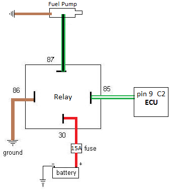
Simply put, this is a location on where to tap into the fuel pump circuit in order to energize the fuel pump via LSx computer control. I myself have isolated the fuel pump circuit before the DME relay. I see no reason for two relays in the fuel pump circuit and do not want to use the expensive and often problematic DME relay...but rather a common and readily available bosch/tyco 30A relay. In reality, you are going to be adding a series of fuses and relays to your harness. So, you should dedicate such important circuits to their own independent relays.So, from your notes, only if I were to eliminate the stock DME relay and replace with a stand alone relay would I need to use pin #4 tied to C101-D? But in my case, using pin #4 is not necessary as it is only used in the circuit for O2 sensors.
I dont have the manual handy but yes, only if you plan on utilizing the stock DME relay. If not, it is not needed. However, looking at the schematic, pin 5 is the ground wire to the DME relay at terminal 85b of the relay. However, it may already be grounded directly between the relay and T21 when, according to the schematic, it leaves central electric for some reason and then re-enters quite quickly.Overall, it looks like the only thing that was not correct in "the manual" was that pin #5 should be ground (not "not used").
I think the majority of conversionists are trying to get away from using the DME relay all together.I know that I had some notes on the fuel pump and I know that there was a recent thread regarding that topic. Hopefully with using the stock DME relay and this pin configuration I will be good to go.
No problem!Thanks for your help and notes on this 944-LT1!!!

944-LT1- Moderator

- Posts : 1265
Join date : 2009-06-09
Age : 102
Location : NOTRE DAME
 Re: 14 Pin Connector - Check Please
Ok, Ok, Ok,,,,, I keep trying to fight having to add in any new circuity, mainly because I have no idea what I am doing. I wanted to just plug and play.
However, this seems too easy to do.
New relay:
30 - 12v direct to battery with 15A fuse. Question, can this 12v came from the same 12v on pin #3. Since this is for fuel supply, does it make since to use a switched supply?
87 - where do I pick up 87 for the fuel pump? under the fuse panel on the existing 87 / 87B?
85 - can come from C101-D (or directly from PIN 9 on RED ECM plug)
 Re: 14 Pin Connector - Check Please
Ok, Ok, Ok,,,,, I keep trying to fight having to add in any new circuity, mainly because I have no idea what I am doing. I wanted to just plug and play.
Pin 3 is from 87 on the DME relay.....well, thats having two relays in one circuit which is redundant. But you can do that if you want....I guess.New relay:
30 - 12v direct to battery with 15A fuse. Question, can this 12v came from the same 12v on pin #3. Since this is for fuel supply, does it make since to use a switched supply?
87 - where do I pick up 87 for the fuel pump? under the fuse panel on the existing 87 / 87B?
According to the schematic, its a straight shot from the fuel pump to pin 4 at T21. But to check, simply pull the DME relay out of the fuse panel and apply +12vdc to pin 4. The pump should turn on. If so, yes, you can just hook up this wire to 87 on the new relay.
Excellent! You got it!85 - can come from C101-D (or directly from PIN 9 on RED ECM plug)

944-LT1- Moderator

- Posts : 1265
Join date : 2009-06-09
Age : 102
Location : NOTRE DAME
 Re: 14 Pin Connector - Check Please
Thanks for clearing this up... It sure takes alot of the guess work outta things!

spence- Posts : 684
Join date : 2009-07-21
Age : 41
Location : St.Catharines, Ontario, Canada
 Re: 14 Pin Connector - Check Please
Always glad to help 

944-LT1- Moderator

- Posts : 1265
Join date : 2009-06-09
Age : 102
Location : NOTRE DAME
 Re: 14 Pin Connector - Check Please
One more question.... Is the alternator wire (on the porshce) ok to hook up directly to the CS130 "L" terminal? Do you have to add a resistor to increase the resistance? I think I read somewhere that the "L" terminal has to have over 35ohms of resistance for the alternator to work properly.
Thanks!
Thanks!

spence- Posts : 684
Join date : 2009-07-21
Age : 41
Location : St.Catharines, Ontario, Canada
 Re: 14 Pin Connector - Check Please
and now, officially beating a dead horse.....
But the DME relay is gone with the new 30/40A relay, right (therefore not a redundant relay)? So cant this be used for the PCM and the fuel pump? I am still thinking that switched 12v is a good idea. Check me on this, but if the cars stops running, say in an accident, the switched power will kill the FP? 12v directly to the relay would allow it to run?
New relay:
30 - 12v direct to battery with 15A fuse. Question, can this 12v came from the same 12v on pin #3. Since this is for fuel supply, does it make since to use a switched supply?
Pin 3 is from 87 on the DME relay.....well, thats having two relays in one circuit which is redundant. But you can do that if you want....I guess.
But the DME relay is gone with the new 30/40A relay, right (therefore not a redundant relay)? So cant this be used for the PCM and the fuel pump? I am still thinking that switched 12v is a good idea. Check me on this, but if the cars stops running, say in an accident, the switched power will kill the FP? 12v directly to the relay would allow it to run?
 Re: 14 Pin Connector - Check Please
Keep beating that horse. The more questions you ask the less I have to ask later.
Arthropraxis- Posts : 1103
Join date : 2009-09-02
 Re: 14 Pin Connector - Check Please
Im not too sure about 35 ohms. But, On my LT conversion, I hooked the blue wire to my cs130 and it worked fine. The blue wire already goes to a resistor (light bulb) in the dash which is grounded termporarily which trips the alternator to charge.One more question.... Is the alternator wire (on the porshce) ok to hook up directly to the CS130 "L" terminal? Do you have to add a resistor to increase the resistance? I think I read somewhere that the "L" terminal has to have over 35ohms of resistance for the alternator to work properly.
Im not sure I follow what youre saying but youll have a relay for the LS computer which is switched by the stock 944 ignition switch. Once the 944 ignition switch sends voltage to the LS computer relay, the computer will energize (via c101d) the fuel pump circuit relay and hence the fuel pump circuit. Im thinking what youre asking is can you use the DME relay as a relay for the LS computer??? Maybe rephrase?But the DME relay is gone with the new 30/40A relay, right (therefore not a redundant relay)? So cant this be used for the PCM and the fuel pump? I am still thinking that switched 12v is a good idea. Check me on this, but if the cars stops running, say in an accident, the switched power will kill the FP? 12v directly to the relay would allow it to run?
I think I lost ya

944-LT1- Moderator

- Posts : 1265
Join date : 2009-06-09
Age : 102
Location : NOTRE DAME
 Re: 14 Pin Connector - Check Please
LT1 is right, the PCM supplies a (+) signal to an external FP relay. Ted, I looked over your electronics sheet from SSP and then the 944 schematic to come up with this diagram which is exactly what LT1 is preaching....Keep it simple and get rid of the Factory DME RELAY. No relays on relays.....just headache later on......
At the time of this drawing, I had the Fuel Pump relay inside the fuse box and #87 wired right into the driver's side of EMPTY Fuse #34 with a single spade connector that I didn't trust to not vibrate out...so.....After looking over the schematic again, I see that pin #4 (green/blk) of 14-pin connector ties directly into fuse #34 driver's side and I just reran FP relay #87 wire directly to pin #4 wire (FUSE #34 remains empty).....This is as plug and play as you get.....
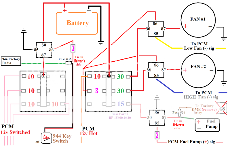
At the time of this drawing, I had the Fuel Pump relay inside the fuse box and #87 wired right into the driver's side of EMPTY Fuse #34 with a single spade connector that I didn't trust to not vibrate out...so.....After looking over the schematic again, I see that pin #4 (green/blk) of 14-pin connector ties directly into fuse #34 driver's side and I just reran FP relay #87 wire directly to pin #4 wire (FUSE #34 remains empty).....This is as plug and play as you get.....


xschop- Posts : 2711
Join date : 2009-06-09
Location : OKC
 Re: 14 Pin Connector - Check Please
I printed off your diagram when you first posted that; Nice!! very simple... This is the way I'm going to run my wiring (except for the fan relays). I want both fans to run when the high speed relay is triggered. I posted a diagram last week showing how I'm going run the relays.
I'm using the Summit universal rad that is listed in the manual and Mercury Cougar V6 radiator fans (alot of Mustang guys use these and say they flow 3400CFM). The fans fit perfectly on the summit radiator. I'll post a pic when I get home.
I'm using the Summit universal rad that is listed in the manual and Mercury Cougar V6 radiator fans (alot of Mustang guys use these and say they flow 3400CFM). The fans fit perfectly on the summit radiator. I'll post a pic when I get home.

spence- Posts : 684
Join date : 2009-07-21
Age : 41
Location : St.Catharines, Ontario, Canada
 Re: 14 Pin Connector - Check Please
Also if you use the factory DME relay (G5) you run the risk of being stranded if your factory alarm box drops out the race....which is inevitable on every 944 I've owned.

xschop- Posts : 2711
Join date : 2009-06-09
Location : OKC
 Re: 14 Pin Connector - Check Please
THANKS 944-LT1 and XSCHOP!
I am clear on this now!!
One last thought...
Can this info get consolidated and added to the Wiki? As sure as the sun will rise tomorrow, this topic will come up again.
I am clear on this now!!
One last thought...
Can this info get consolidated and added to the Wiki? As sure as the sun will rise tomorrow, this topic will come up again.
 Re: 14 Pin Connector - Check Please
LT1 deserves the credit on this one. My hunt and peck typing would never get all that info in one post before the board locked up LOL....
I have already copied/pasted what he just wrote to my hard drive so when I build another it's right there with the diagram..... (edited for a better fitted emoticon).....
I have already copied/pasted what he just wrote to my hard drive so when I build another it's right there with the diagram..... (edited for a better fitted emoticon).....

xschop- Posts : 2711
Join date : 2009-06-09
Location : OKC
Page 1 of 2 • 1, 2 
 Similar topics
» 9 pin firewall connector - early cars
» CSR Thermostat Housing Info and Another Alternative
» Help Identify this connector!!!
» CSR Thermostat Housing Info and Another Alternative
» Help Identify this connector!!!
944Hybrids: 924/944/968 and 928 V8 Conversions :: Technical Stuff (other than motors) :: Electrical Mods
Page 1 of 2
Permissions in this forum:
You cannot reply to topics in this forum
 Home
Home
» Best engine uprights/plates
» LEAKING TPC HYDROBOOST
» HYDRAULIC THROWOUT/RELEASE BEARING NOT ENGAGING FULLY
» Fesler Saratoga Top
» Ray's 1987 944 LS1 Build & Swap
» LS 982 5speed project here
» LT1 Spark Plug make and model
» 928 5-speed kit
» Slave Cylinder Spacing from Clutch Fingers